How to design a rectifier safety transformer for feed to voltage controllers of 5Vdc,1Adc and 2x12Vdc,0.1Adc with RC-loading accordance with IEC 61558
Technical specification relevant only for design
Electrical data and schema
| Input voltage: | 230V, +10%, -10%, sinusoidal |
| Frequency: | 50Hz |
| Min. output voltage 1: | 8Vdc, at -10% of input voltage and 5% voltage ripple |
| Nominal output voltage 1: | 9Vdc, at at the nominal input voltage |
| Nominal output current 1: | 1Adc, RC load |
| Nominal output voltage 2: | 2x12dc, at nominal input voltage |
| Nominal output current 2: | 0.1Adc, RC load |
| Voltage ripple: | 5% |
Ambient and operating conditions:
| Ambient temperature: | 40°C | |
| Mode of operation: | Continuous | |
Insulation:
- Safety transformer as per IEC 61558
- Insulation class E
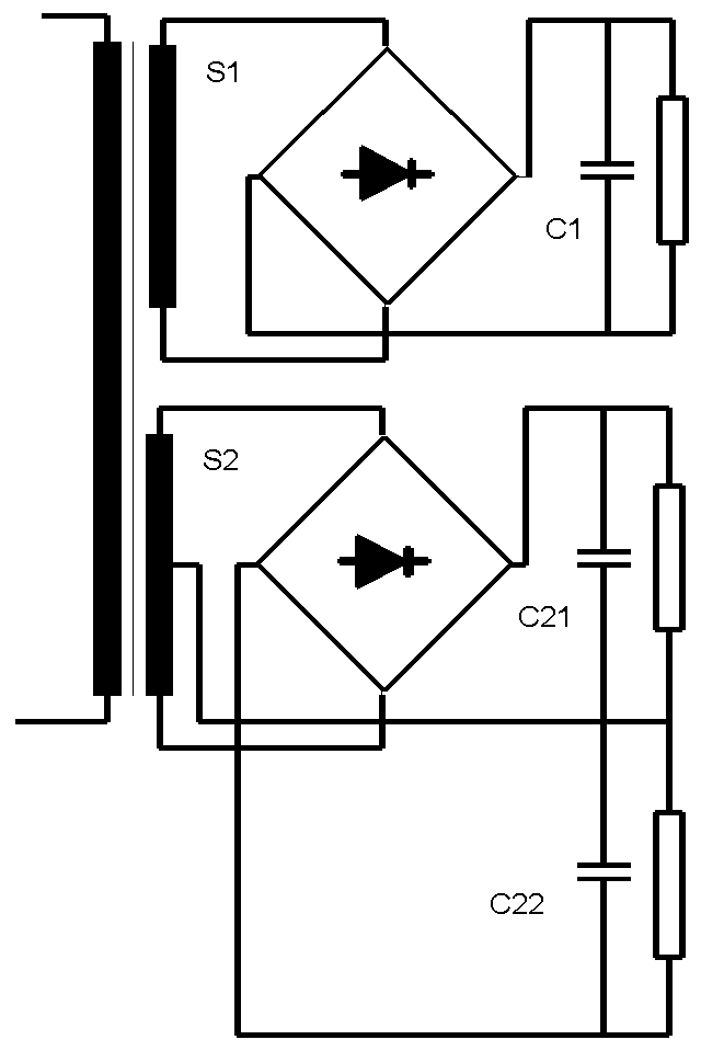
Schema:

Criteria for design
The 5V voltage controller can not run in overload. In short circuit the primary fuse will disconnect the transformer from net.
The short circuit in the 12V output makes no problem because the temperature ris very low: 166<215°C. That means that the 12V winding is inherently short circuit proof.
Insulation class
Max winding temperature in overvoltage operation mode <= 115°C
Output voltage
A rectifier transformer with RC load, for which the minimum and maximum output voltages are described, must adhere to the prescribed tolerances. For that reason, the transformer is firstly designed in accordance with the criterion of DC voltage regulation (criterion = 1) and then tested to IEC in the test program.
The output voltages of 2x12Vdc are grouped together as one single voltage of 24Vdcr. After our design work, we must provide for a tap in the middle of the calculated number of bifilr wound windings. If the designed value amounts to that of capacity C, then connectors C21 and C22 must have the value of 2*C.
Regulation of the DC output voltage
Note that the program supports the regulation of the AC secondary voltage and the regulation of the DC rectifier voltage.
Output voltage ripple
Output voltage ripple can be prescribed as follows:
Ripple = 100*(Udcmax-Udcmin)/(Udcmax+Udcmin)
The program calculates the magnitude of the required capacity of the smoothing condensers for the prescribed DC voltage ripples.
Bobbin
In this power range, recourse is had almost exclusively to a double-section bobbin unit.
Impregnation
The bobbin and the window of the core is injected under pressure. In this method, we save on the quantity of potting compound with the same voltage resistance as a potted transformer, and we don’t need a case.
Induction
We select our induction on the basis of a voltage level below the input voltage of -10%, between 1.2 and 1.4.
Procedure of design
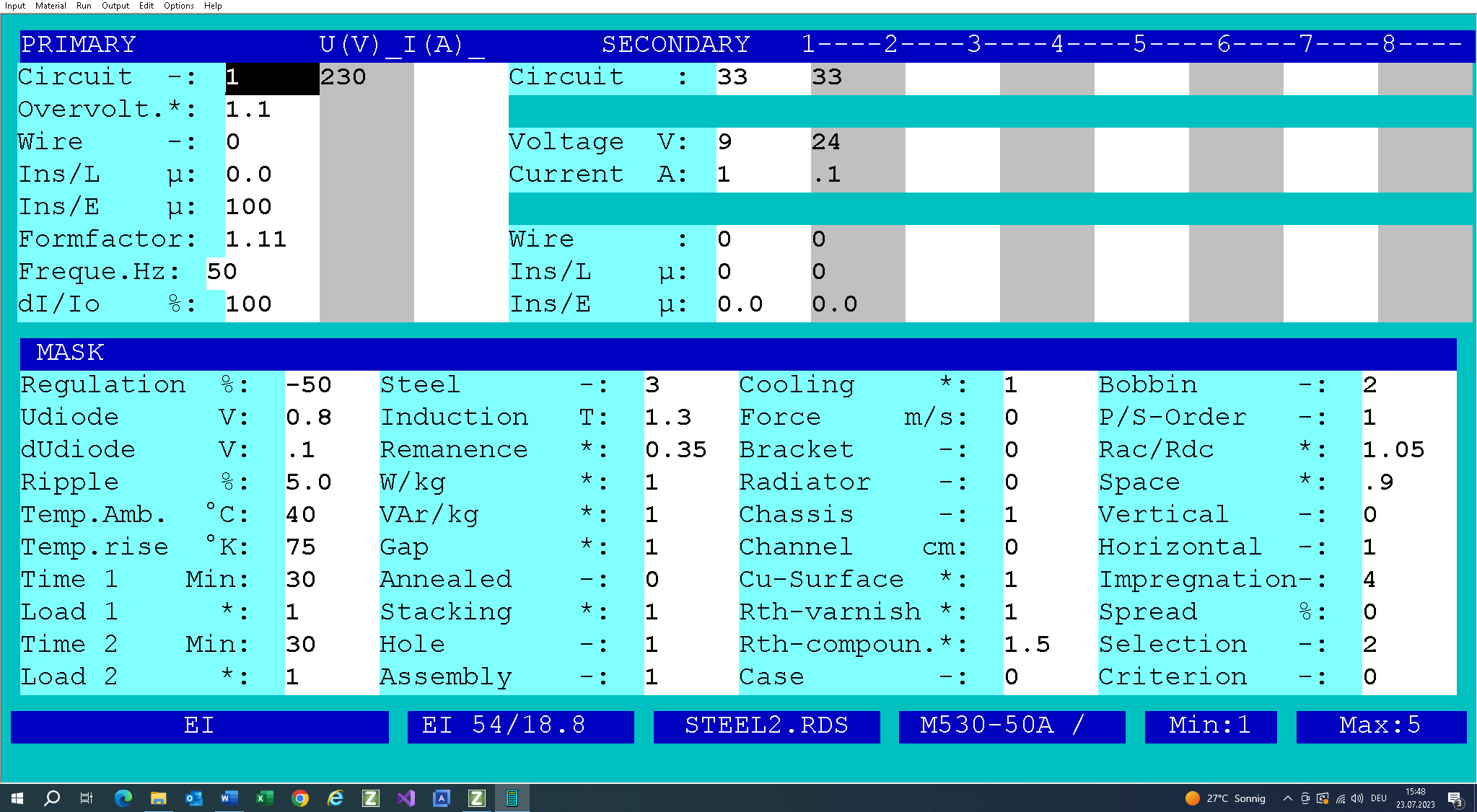
Fill out the input mask as follows. If you need any help, press function key F1. There is extensive description for each box. You can open the input file RaleInput_005.TK1:

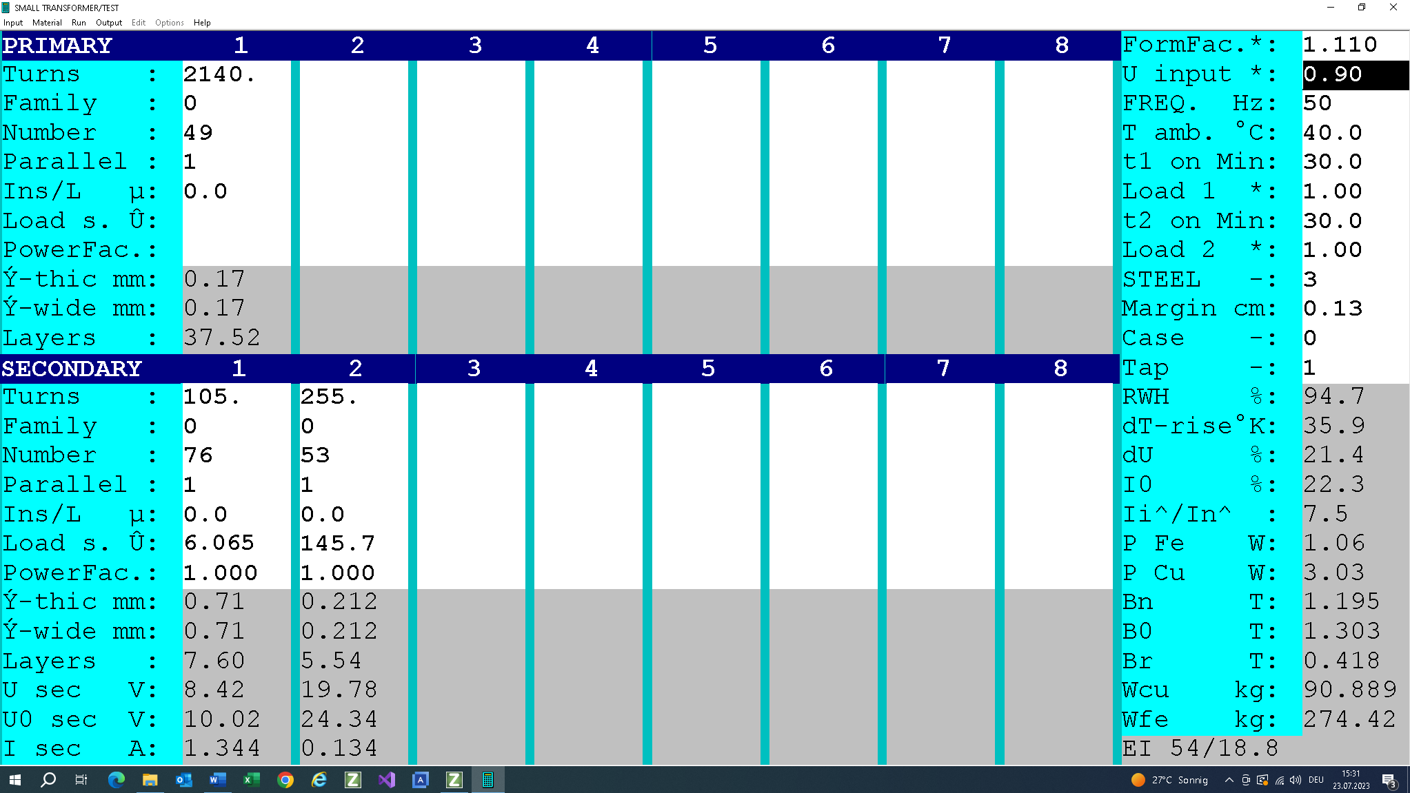
Now two PDFs can be printed (click below):
This is followed by checking of the design data.
- Firstly we check the winding data and the filling factor (94%<100%).
- The next teat is the max. winding temperature =94.5<115°C
- The nominal fuse current should be between 0.2 amd 0.25A ,only for protection in short circuit operation mode of the 9V winding.
- In the “Strana3_12V_CC.PDF” (see above) the temperature of the 12V winding on the “load” of 1mOhm = 166°C < 215°C is tested.
Now follows the test under the input voltage of 207V:

The results can be printed (click on the following link):
The min. DC output voltage at the 207V input voltage and the DC output current of 1A is 8.5V!